In the process of pump operation, so that the two shafts have been in the state of connection, known as the coupling.
Under normal circumstances, pneumatic diaphragm pump and magnetic pumps do not require an elastic coupling.
Couplings are generally used to connect two shafts and transfer motion and torque between them;
Have the ability to absorb oscillations and gentle shocks;
Can be used as a kind of safety equipment to avoid being connected to accept too large load, the effect of overload protection;
When the shaft is connected with a coupling, the two shafts can be separated only after the machine is stopped and disassembled.
Fixed coupling: it is required that the center line of the two shafts connected should be tightly aligned;
Movable coupling: Allow certain device errors for both shafts.
Elastic coupling: the elastic elements between the different data, can compensate the displacement between the two axes within a certain range, as well as the effect of cushioning and damping.
The two axes connected by the coupling often have relative displacement and deflection to some extent due to the influence of manufacturing and device error, deformation after bearing load, bearing wear, imbalance of rotating parts and temperature change.
A variety of structural measures should be taken to make the coupling compensate for various offsets, otherwise additional loads will be caused in the planning of the shaft, coupling and bearing, leading to the deterioration of the operation.
The displacements between the two axes are: axial displacement, radial displacement, angular displacement and inductive displacement.
A. The structure is simple, convenient for protection, and can transfer large torque;
B. However, the relative displacement between the connected axes lacks the ability to compensate;
C. There is a high requirement for the neutrality of the two axes. If the two axes have relative displacement, additional load and severe wear will be caused on the shafts, couplings and bearings, which will seriously affect the normal operation of the shafts and bearings;
In addition, the shock and oscillation cannot be absorbed gently when the load is transferred.
Low speed, high torque, stable load, short and rigid shaft connection
Varieties of 3.
Flange couplings and sleeve couplings are available.
A. Composition: two half couplings with flanges and A set of bolts;
B. Operating principle: Two half couplings with flanges are fastened to the two shafts and then bolted to the two halves to transmit motion and torque.
C. Aligning method: 1. Align the two half couplings with protruding shoulders and grooves, and the half couplings shall be connected with general bolts; 2.
(The torque is transmitted by the collision force generated by the pre-tightened general bolt touching the surface at the flange edge;
The hinged hole bolts are aligned, and the screws accept the moment of kneading and shearing.
D. Application: low speed, high torque, stable load, short and rigid shaft connection.
E. Simple structure and large transfer torque;
Strong transmission, good for neutral;
Simple and widely used;
But it has no function of displacement compensation.
Choose according to the specification.
A. Composition: select key or pin to connect the two shafts through A common sleeve.
B. Advantages: simple structure, convenient production, low cost, small radial scale.
C. Defect: axial movement is required during installation and disassembly.
D. Application: in the case of small diameters of the two axes, high neutral precision of the two axes and stable operation, it is used in the case of small torque transfer.
Flexible coupling
Varieties of rigid movable couplings (inelastic element couplings) : cross slider couplings, universal couplings and drum tooth couplings.
A. Composition: two external sleeves with internal teeth and flanges, and two internal sleeves with external teeth;
B. Operating principle: the two internal sleeves are connected to the two shafts with keys, and the two external sleeves are connected with bolts. Torque and movement are transferred through the engagement of the inner and outer teeth.
C. Features: In order to compensate the relative displacement of the two axes, the tooth of the outer tooth ring is made into a drum tooth, and the tooth tip is made into a sphere with the center line on the axis. A large gap is left between the tooth tip and the tooth side.
Through the top gap and side gap between the meshing teeth, it has the function of allowing radial, axial and angular inductive displacement compensation between the two axes.
High speed (up to 3500r/min), can transfer a large torque (up to 106N·m), and can compensate a large inductive displacement, high operation, the device accuracy requirements are not high, to be smooth;
D. Defects: high quality, difficult production and high cost.
E. Application: widely used in large heavy machinery and equipment such as cars.
A. Structural features: it is connected by the semi-coupling shaft 1 and 3 (left and right sleeves) and the floating plate 2 (cross slider), and the two shafts roll together;
The tenon of the floating disc may slide in the groove of the half coupling;
The conflict is bigger, want to try smooth.
B. Advantages: small radial scale and simple structure
C. Defects: poor impact resistance, easy friction between the sliding block and the groove, and smooth;
The radial displacement of the cross slider will cause a large centrifugal inertia force, which will bring additional load to the shaft and bearing.
D. Application: it is often used in situations where rigidity is large, rotation speed is low and impact is small.
Universal coupling
A. Structure: It is composed of A cross shaft, two universal joint forks and four needle roller bearings;
The center of rotation (axis) of all rolling pairs intersects at point O, and the Angle between the two axes is alpha;
A device (coupling) used to transmit motion between two intersecting axes at varying angles.
B. work principle: when one revolution axis Ⅰ shaft Ⅱ will turn a week, the two axis of uniform transmission ratio is 1;
However, the instantaneous transmission ratio of the two axes is not always 1, but changes periodically.
This characteristic of universal joint is called inhomogeneity of instantaneous transmission ratio;
For a single universal joint, when there is an Angle between the input axis and the output axis, the angular velocity of the two axes is not equal, that is, the universal joint has unequal velocity;
The greater the Angle between the two axes is, the more significant the velocity oscillation of the driven axis is.
Therefore, should be between 35° and 45°.
In order to avoid the main and driven axis angular velocity is not equal;
In order to completely eliminate the defects of driven shaft variable speed transmission in the universal joint, it is often used in pairs.
C. Advantages: it has great angular compensation ability, compact structure and high transmission efficiency;
D. Defects: Additional dynamic load will occur in the transmission, and the speed should not be too high;
E. Application occasions: mainly used in the transmission of two intersecting shafts, medium and low speed occasions such as heavy, medium and light load, such as machine tools and cars.
F. Satisfactory conditions for double universal joints:
In order to achieve a stable transmission ratio, the organization shall be satisfied with the following three conditions :(1) the three axes of the driving axis, driven axis and central axis shall be located in the same plane.
(2) The included Angle between the driving shaft, driven shaft and the central shaft shall be equal:
(3) The fork surface of both ends of the center axis should be located in the same plane.
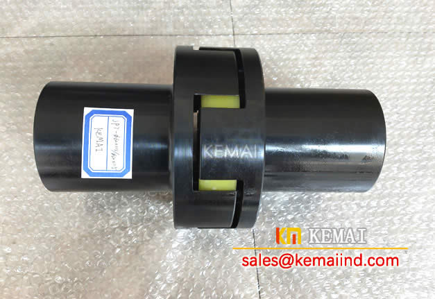
(2) Commonly used elastic couplings include two types: an elastic sleeve column pin coupling and an elastic column pin coupling.
A. Structure: structurally similar to flange couplings, only rubber sleeve printed instead of connection bolts;
B. Principle: the elastic deformation of the elastic sleeve is used to compensate the relative displacement of the two axes;
C. Features: The elastic sleeve column pin is simple in making, convenient in assembling and disassembling, with low cost, but the elastic sleeve is easy to wear and has a short life.
D. It is suitable for: two-shaft connection of medium and small torque transmission with stable load, positive rotation or frequent start and high rotation speed.
A. Structure: the column pins made of some non-metallic materials are placed in the flange holes of the two half couplings to complete the connection of the two half couplings;
Nylon is commonly used for column pin information, other flexible non-metallic materials are also available.
B. Principle: The elastic deformation of the elastic column pin is used to compensate the axial displacement of the two axes;
C. Features: The elastic column pin coupler can allow large axial movement, but the compensation for radial and angular displacement is not large.
Its structure brief, production brief and protection convenience.
D. For: light loading
