Circular arc gear pump is a positive displacement pump. It consists of two gears, the pump body and the front and rear covers to form two closed Spaces.
Forming a vacuum, the liquid is sucked in, and the volume of the space on the meshing side of the gear decreases from large to small.
The liquid is forced into the pipe.
The suction and discharge cavities are separated by the meshing lines of the two gears.
The circular arc gear pump adopts the most advanced one point continuous contact gear of the conveying pump, that is, double circular arc plus sine curve compound into the tooth shape, can eliminate the involute gear conveying pump.
He was awarded the third prize of science and technology progress by the education commission.
The circular gear is in continuous contact between two meshing tooth profiles, which will not produce oil trapping phenomenon, which solves the vibration, noise and bearing load increase of the involute gear pump caused by oil trapping phenomenon.
So the circular arc gear pump has the efficiency, the noise is low, and has the good energy saving effect.
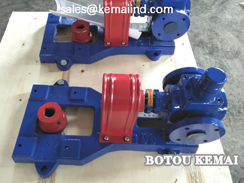
Arc gear pump is mainly composed of gear, shaft, pump body, pump cover, bearing sleeve, shaft end seal.
The gear is made of double arc sinusoidal tooth.
Low noise, long life, high efficiency.
The pump gets rid of the shackles of the traditional design, so that the gear pump in the design.
Production and use have entered a new field.
Step 1: place the unit on a foundation with anchor bolts.
Put a pair of pads between the base and the foundation for forward use.
Step 2. Release the coupling and place the level on the pump shaft and base respectively.
Adjust the wedge pad to make the unit level. After alignment, tighten the anchor bolt properly.
Step 3. Fill the base with concrete and anchor bolt holes.
Step 4: wait for the concrete to dry.
Check whether the base and anchor bolts have undesirable looseness and other phenomena.
After inspection, the end face bolt should be tightened after qualified tightening.
Gear pump force to symmetrical uniform, tight side disk rotor.
If encountered acerbity, gear pump should loosen the bolt to tighten again.
Re-check the levelness of the pump.
Step 5. Correct the coaxiality of the pump shaft and motor shaft, allowing a deviation of less than 0.1 mm on the circle at the coupling.
The clearance between the two couplings shall be 2~3 mm on the end of the couplings.
The difference between large and small gaps shall not exceed 0.3 mm.
Step 6. After connecting the pipeline and determining the rotation direction of the prime mover, connect the coupling and check the concentricity of the pump again.
Step 7, find out the pump allowed high speed.
And work on site at high speed;
Be sure to let the fluid into the inlet, try not to dry and idle;
Step 8. In order to prevent sundries from falling into the machine during installation, cover all holes of the unit.
Step 9. Clean the inlet and outlet pipeline before opening the pump.
Add a filter at the inlet of the pump to prevent debris from entering the pump.
The 10th step, arc gear pump oil pump inlet and outlet do not meet the opposite.
Causing the pump to fail.
Step 11: check the unit after 3 to 4 hours of actual test operation.
If there is no bad phenomenon, the installation is considered qualified.
